Choosing The Correct Pump For The Mississippi Alluvial Aquifer: Pump Doldrums
DR. JOE HENGGELER
PORTAGEVILLE, MO.
Irrigators in the Southeast Missouri region (SEMO) are blessed because
underneath the land they stride rests a tremendous bounty – the
Mississippi Alluvial Aquifer. This awesome groundwater resource is
abundant, of good quality, and shallow (thus cheap to capture). I came
to Missouri 16 ½ years ago from west Texas, and our water situation here
in SEMO is truly a world apart from theirs. The farmers in the St.
Lawrence region of Texas have irrigation wells 450 feet deep that today
produce 10-25 GPM. They’d plumb 30 to 50 of these wells together with
4-inch pipe and carry on. Back in the day when they were still using
furrow irrigation (albeit very short rows, ≈ 700 ft), I use to comment
that the output from TWO wells was going into a single water furrow!
Working in that area was a primer on efficient irrigation. Thirty years
ago we worked together to introduce sub-surface drip irrigation (SDI).
In a recent visit back there I learned that 95 percent of their cotton
acreage is now SDI. In one of the visits back there I was explaining to
the German extraction cotton farmers there about our 2-inch wells that
we use to fill up water tanks, and that they could make 100 GPM – and
were run with centrifugal pumps. What they would give for a water
resource like that!
So getting back to SEMO and its water abundance: in reality there is,
however, one problem we do have. Furrow or flood irrigation with
electric pumps is problematic. The reason for this is that high- flow
low-head (HF-LH) pumps we use can become extremely
inefficient with small changes in the water table depth (or even changes
in friction loss!). Diesel- and propane-driven pumps don’t have this
problem since they can rev up or down following that fluctuating water
table. Also, those electric irrigation pumps used on center pivots avoid
this problem since the few feet of change in the water table are
relatively small in relation to the pump’s total dynamic head (TDH) requirement for pressurizing a pivot. Additionally, HF-LH
on electric pumps with variable frequency drives – which are being seen
more and more frequently in SEMO these days – are also spared this
problem.
Figure 1 is a pump characteristic curve for a typical electric pump used
to water furrow-irrigated fields. It is a single stage pump. Its best
efficiency point (BEP) lies at 1,830 GPM and 46.0 feet
of head; at this point pump efficiency is 80 percent. Note on the pump
curve that there is a fairly flat stretch of section to the left of the
BEP that I am designating “the doldrums.”
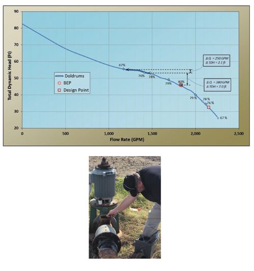
Fig. 1. A characteristic curve
for a typical single stage pump used in SEMO for furrow irrigation. The
Best Efficiency Point (BEP) is shown at Q = 1,830 GPM and TDH = 46.0
feet. If the pumping water level (PWL) drops 7 more feet, flow rate is
reduced by 380 GPM. At that location the operating point of the pump
has reached the sensitive flat, doldrums area. Just 2.1 more feet drop
in the PWL and Q drops another 250 GPM. The design point should be to
the right of the BEP.
Fig. 2. Sounding a well’s Static Water Level by removing an air relief
valve and dropping an e-line inside the column pipe while the pump is
off.
The Doldrums. Today
the term doldrums connotes a period of personal stagnation, or, in
popular parlance, “being in a funk”! However, during the nineteenth
century when Richard Henry Dana penned Two Years Before the Mast,
doldrums was a nautical term referring to places in the seas where at
certain times of the year low barometric pressures caused mirror-smooth
seas. In the pre-steamer days ships could end up languishing stationary
in the doldrums day after day, as water, food supplies, and nerves
dwindled away, just as Dana faced sailing around Cape Horn.
Pump curves that are flat, or have segments that are flat, can be pose
serious problems in situations where fluctuating water tables exist. As
mentioned, the pump in figure 1 has its BEP at 1,830 GPM and 46.0 feet of head. Should the water table drop just 7 feet off this “sweet spot”, its TDH would now be 53 feet (note: water table ↓ = TDH
↑), and flow would decrease to 1,450 GPM (a 21 percent drop). Notice
that almost a quarter of the pump’s flow rate has been lost with that
first a 7-foot drop in water table. That amount of head loss is not
really very much. From 1957 to 2013 there was an average 3.9 feet swing
each year in the static water level (SWL) during the
200-day pumping season (April 1 to Oct. 15). These data comes from
records from the Missouri Department of Natural Resources’ (MDNR)
observation well at Malden, one of the nine monitored observation wells
in the Mississippi Alluvial aquifer in SEMO. In some years the Malden
spread was almost 8 feet. When you factor in well drawdown on top of
this to arrive at the pumping water level (PWL)
– the item that pump actually responds to – it is almost for sure that
the Malden water table spread will have HF-LH pumps in the region
swinging in and out of favorable efficiency ranges. Note that pump
efficiency levels are recorded on the pump curve (fig. 1). If that news
isn’t gloomy enough, consider this: Malden’s 3.9 foot swing is on the
smaller side. The average swing for the nine observation wells is 7.5
feet; Quilin has an 18.1 foot seasonal swing!
Unfortunately, things could get worse. With the TDH value of this pump now at 53.0 feet (remember we have just gone 7 feet away from the BEP where the TDH was at 46.0 ft), the pump is operating at the cusp of the doldrums region where things go real bad, real fast. Now with just 25 inches of additional head loss at this point, 17 percent of the present 1,450 GPM vanishes, and we are down to a mere 1,200 GPM!
The debilitating loss of water caused by the increase in TDH
doesn’t come only from a dropping water table; at the flow rates we are
talking about, adding an 8-inch surge flow valve inline would have
engendered the same flow loss. These water table swings are inevitable.
The HF-LH irrigator fights back by, first, gaining knowledge of the SWL and PWL at his well and, secondly, using this knowledge to choose the correct pump.
How to Manage. Having a
resource like the Mississippi Alluvial Aquifer at our disposal is a
blessing. However, we still have problems irrigating out of this shallow
aquifer if we use regular electric pumps for furrow irrigation. So how
do we get around the problems for the HF-LH systems?
1. Install air lines in your wells. Air lines of
themselves won’t solve the problem, but they do give you insight into
what is occurring. These homemade devices cost just about $35 to
fabricate. They need to be put in when a new pump is being installed
(fig. 2). An air line is to an irrigator what a stethoscope is to a
doctor. You do not know if there is a problem nor its extent unless you
can assess the situation. For information on air lines: http://crops.missouri.edu/irrigation/
2. Install a variable frequency drive unit.
3. Study your pump curve to see if it has a doldrums area that should be avoided.
4. Choose a location on the right side
of the BEP as your design point (c.f., Fig. 1). In this case, if
increased head occurs it will shove the operating point to regions of
higher efficiencies, not lower efficiencies.
5. If you know that you will be replacing the pump in a well, begin collecting actual information on Q and PWL
while the old unit is still in place. a. It would be wise to purchase a
flow meter. Install it and begin collecting this information. The
investment in the meter would yield dividends in the future with lower
energy costs. Based on $0.17/KWH and 80 acres with 12 inches applied,
there would be a $200 per year savings on energy costs had the irrigator
chosen a pump based on the design point versus one based on the BEP (c.f., fig. 1). At those rates the investment in the water meter would soon be recaptured.
6. While your well is being developed insist that the drillers collect both Q and PWL data. This will go a long way in getting the right pump for you.
Unfortunately, when site-specific data is unavailable, irrigation companies are, to a degree, blindfolded in getting the best HF-LH for their electricity user customers. This is due to the fact that predicting exactly where the PWL
will be in a new well is difficult – and also it’s a moving target,
with in-season changes, drought period changes, and even changes in
commodity prices affecting when the aquifer’s SWL begins to move south.
We have seen where being off by just inches on the TDH value can lead to experiencing big water and efficiency losses.
Irrigation professionals today are better equipped in estimating a reasonable TDH value to couple with the GPM
amount the farmer is shooting for. This is in great part due to the
MDNR’s network of nine observation wells in the Bootheel. Triangulation
of the water depth at any three of these wells would be a good estimator
of the SWL in your well, or while it’s off you could
sound it through some sort of access port (figure 3). Knowing what the
range of expected in-season SWL values will be is an excellent starting off point in determining what TDH value is needed. Also, friction loss, which accounts for about 5 percent of TDH, can be precisely accounted for. However, now comes a big unknown: what will be the drawdown for the Q being sought?
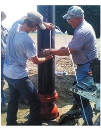
Fig. 3. Sounding a well’s Static
Water Level by removing an air relief valve and dropping e-line into
the column pipe while the pump is off.
As an estimate use 1 foot of drawdown for every 100 GPM desired. Thus if
you are planning on 2,000 GPM figure 20 feet of drawdown; if 3,000 GPM
is your goal, plan on 30 feet. Add these to your July SWL
and throw in a bit for friction losses. While these are good estimating
tools, nothing beats having an air line in place. A smoke detector in
every home, an air line in every well!∆
DR. JOE HENGGELER: Irrigation Specialist, Commercial Agricultural Program, University of Missouri Delta Center